

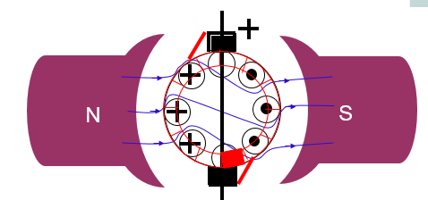
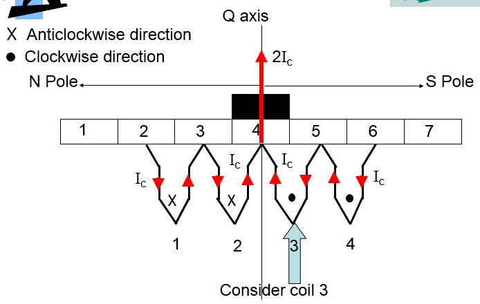
Let us consider a few commutation segments and see process of reversal of current in the coil step by step. Suppose the dc motor to rotating in anticlockwise direction. Observe the direction of current through the coil 3 during the process of commutation. Initially when the coil 3 (commutator segment 4) is under the S pole the current Ic through it is in clockwise direction and through the brush is 2Ic as can be easily deduced from the figure. The brush is in contact with commutator segment 4 completely.
As the motor rotates, brush comes in contact with the CS-5. Total current through the brush remains same but the contribution of C-3 changes to I5 from Ic . Rest of the current goes through the coil.

On further rotation half of the CS-5 comes in contact with the brush , thus there is equal contribution from CS-4 and CS-5 to the brush. Notice the current through the coil 3 will become 0. This is a short circuit condition. If there is even a small amount of induced voltage, it would result in large current through the coil thus damaging the winding.

Further rotation brings majority of the current to brush through CS-5. And the direction of the current in the coil 3 has reversed.

And finally the next step CS-4 is completely removed from the brush contact. There is spark due to interruption of current through C-4.

Ideally the process of commutation should have linear variation of current with time.

The time required to change the current through a coil from Ic to -Ic is called Commutation Period (Tc)
If Time taken > Tc, then under or delayed commutation
If T<Tc , then over or accelerated commutation.
Accelerated commutation produces no trouble, however the delayed commutation results in increase in spark.

There are 3 methods to obtain Sparkless commutation:
- Resistive commutation
- Voltage commutation
- Compensating commutation
See guys, our main concern is to reduce the time delay in the commutation process. Because this is a transient stage, a time constant factor is involved between the steady stages. The time constant L/R reduces with increase in resistance, hence we can obtain a sparkles commutation by Resistive commutation method.
Current through the coil changes from Ic to –Ic. Reactive voltage is induced due to rate of change of current. Owing to lenz law, the induced emf will try to reduce the rate of change of current. This would result in under commutation. To reduce this effect we have interpoles placed along the Q-axis winding placed in series with the armature winding to oppose the induced reactance voltage. Reactance voltage decreases, commutation process improves.

The rate of change of flux is high under the pole (non commutating zone).This could result in high induced emf in the commutators there and damage the winding due to high current(flashover). To reduce this effect, compensating winding is provided in the pole shoe with polarity opposite to that of armature. They not only reduced rate of change of flux but also undo the shifting of the magnetic neutral axis.


Enter your comment... can I get a simplified commutation process only
ReplyDeleteI am wondering what is the factor or reason that causes the presence of number 1.11 in the law of reactance voltage for sinusoidal commutation?
ReplyDelete