
Rubber bands- they can be stretched by our hands. Ever wondered how other materials such iron, copper, superconductors etc. could be stretched? A universal testing machine (UTM), also known as a universal tester, materials testing machine or materials test frame, is used to test the tensile strength and compressive strength of materials. The "universal" part of the name reflects that it can perform many standard tensile and compression tests on materials, components, and structures.
WHAT'S NEW?
Loading...
Showing posts with label Machine. Show all posts
Showing posts with label Machine. Show all posts


It is a process where the state of
the power system is estimated.All the telemetry values of power flow, voltage
levels are considered.These values are used to calculate the phase angle of the
voltage which helps in determination of the power flow between two nodes in the
power system as the power flow is directly proportional to sine of that angle.
The power flow monitoring is
important for the power system as any kind of overloading on the lines can lead
to cascade tripping and can also lead to black out.
Even after getting acquainted to the various concepts related to electrical engineering, there is always one important concept which most electrical engineers, including me, tend to forget. What exactly is reactive power? What is power factor? Why is it so damn important? What do you actually mean by lag and lead? So this discussion would be an informative recap into the basics.

Disclaimer: You could find this highly descriptive, but a short circuit is the only thing ‘short’ in Electrical Engineering. :P

India has one of largest electrical networks in the world. Different types of sources and load are feeding and consuming power from this massive mesh called the NATIONAL GRID. All the sources are connected in parallel. Parallel operation of the generators improves the reliability of the power system by allowing the isolation of few generators for maintenance or under fault condition without any loss of load.
Maximum percentage of power generation is done by Coal based and hydro-based power plants which use synchronous generators as the generating unit. Wouldn't it be interesting to understand how these power plants control the flow of power and maintain such a large network where there is so much variation of load time to time. Let’s become adept over it.
To begin with lets analyze two synchronous generators working in parallel and observe how various circuit parameters are affected. There are two ways how the generating unit control the power flow to the grid:
Maximum percentage of power generation is done by Coal based and hydro-based power plants which use synchronous generators as the generating unit. Wouldn't it be interesting to understand how these power plants control the flow of power and maintain such a large network where there is so much variation of load time to time. Let’s become adept over it.
To begin with lets analyze two synchronous generators working in parallel and observe how various circuit parameters are affected. There are two ways how the generating unit control the power flow to the grid:
- Adjusting the Driving Torque
- Adjusting the Excitation Voltage
NO LOAD OPERATION:
Let us consider two alternators connected in parallel and
are unloaded. With respect to external circuit, both the emfs of generators are in
phase and with respect to the local circuit they are in phase opposition.


Driving torque can be varied by controlling the gate
openings of the hydro turbines or by throttle openings of steam turbine. In
this article, we have considered cylindrical rotor generator but the results
are equally relevant to salient pole generator too.


It is necessary that the machines impedance shouldn’t be
purely resistive. If they are purely resistive, then the circulating current
would be in phase with Ec (fig ii) and thereby both will act as generator. There would be no tendency of auto equalization of speed. It implies that there would be frequency mismatch leading to power surges and harmonics.
ON LOAD:

 The load current IL
= Ia1 + Ia2 (can be seen in the circuit beside). Increasing the driving torque would result a
change in the amount of load shared, the currents Ia1 and Ia2
and respective power factors. Howsoever, the load current IL remains
constant. First, we’ll see how load sharing varies.
The load current IL
= Ia1 + Ia2 (can be seen in the circuit beside). Increasing the driving torque would result a
change in the amount of load shared, the currents Ia1 and Ia2
and respective power factors. Howsoever, the load current IL remains
constant. First, we’ll see how load sharing varies. On load operation depends upon the speed-load characteristics of the alternator. Generally these characteristics are not linear. Hence a governor mechanism is used to make them linear as in the figure beside.
If we increase the
driving torque of Gen1, speed increases and the speed-load curve shifts upwards
indicating the increase in speed. Obviously decreasing the driving torque would
shift the characteristics downwards.

Consider the two generators are supplying to a
load PL (=P1+P2 initially). Now if we increase
the driving torque of gen1. It’s speed-load characteristics shift upwards. In
order to maintain the frequency (as the load is constant) the driving torque of
gen2 should be decreased. Thus the dotted lines in the figure indicate the
speed load characteristics of both the generators and the line2 indicates the
frequency of the constant load. Thus the load shared by gen1 increases to P1’
and the load of gen 2 decreases to P2’ but to the end the sums of
loads shared by both the generators would be constant and equal to the total
load PL.
Now let us see how the currents and power factors of each generator is effected.
Now let us see how the currents and power factors of each generator is effected.
At first assume that Ef1= Ef2
and therefore Ia1=Ia2 and the load shared will be equal.

Now increase the driving torque of gen 1 which increases the speed and frequency and thereby increasing the power angle δ to δ1 and the power increases to P1’.
The driving
torque of gen2 is now decreases in order to supply to the load at constant
frequency. Ef2 decreases and power angle also decreases to δ2 and the power decreases to P2’.
More over, this
change in the emfs will lead to a resultant emf Ec. Hence, a
circulating current flows which lags Ec almost 90.. This
current adds up to Ia1 and hence current through gen 1 increases
(indicating that the load shared by this gen has increased). The power factor
angle decreases thereby improving the power factor. The current Ic reduces
the current from gen 2 and there by indicating that the load shared by this gen
is reduced. The power factor angle increases and thereby decreasing the
power factor.
Thus we can conclude that, by increasing the driving torque
on load increases the load shared, current and also improves the power factor.
Potier triangle method
is helpful in obtaining the voltage regulation of synchronous machines. It
gives the value of potier reactance and the armature mmf (reaction) by drawing
a series of curves on experimental basis.
Potier reactance
is the air gap reactance (leakage reactance) of the synchronous machine at full
load (rated voltage and current of armature).
 |
| Circuit Diagram For Determination of Portier Reactance |
Working of a 3 phase Induction Motor
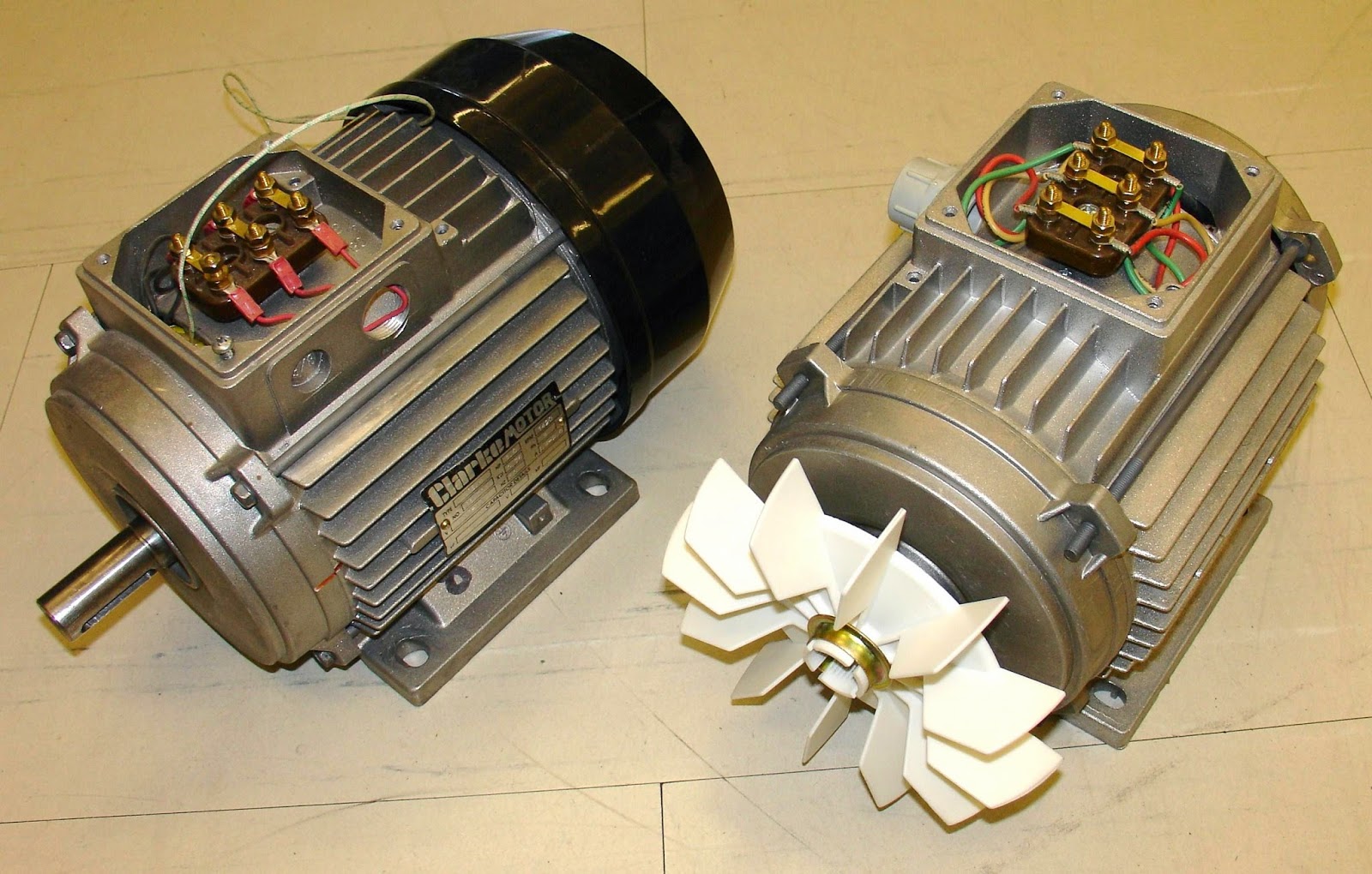
The induction motor works on the principle of Induction and hence the name Induction Motor. The rotating magnetic field produced by the stator cuts through the conductors of the rotor and hence induces voltage. The induced voltage circulates current in the windings of the rotor since the ends of the rotor are short circuited. Current carrying conductor experiences force when placed in a magnetic field. As a result the motor rotates.
What is important for an induction motor to works is a Rotating magnetic field. What is actually a rotating field?
I shall try to explain that through slides of images.
A 3-phase supply consist of same magnitude emf displaced by 120 degrees. Corresponding flux produced are also displaced by 120 degrees. Let us draw these wave forms and find there find their resultant sum for different angles. We find that the resultant of the 3 flux waveform always remain constant for any value of theta. When we plot this magnitude vs. theta graph in polar form we get a rotating magnetic field which is rotating with an angular frequency omega.
Consider the flux produced by the stator is rotating in clockwise direction. Since there is change of flux, there will be induction of voltage. The direction of the current flowing will be such that it opposes the cause of it that is the relative displacement of the flux and conductor. Hence the rotor will rotate in same direction. So 3 phase induction motor is a self-starting motor.

The rotor will always try to make the relative speed to 0 but will not be able to achieve that. As it reaches the Synchronous speed there will be no relative speed and hence no current and no torque. Hence 3 phase induction motor is also called asynchronous motor. However the average speed of the rotor remains almost constant.

Transformer require an AC supply for its functioning. Alternating current flowing through the primary winding creates an alternating flux which links the secondary through a magnetic core. Due to changing flux, emf is induced in the secondary winding. The ratio of voltage appearing across the primary and secondary depends upon their turn ratio, being more specific on the transformation ratio.
This was something too basic which I needed to discuss before I take up the more important topic – Harmonics in transformer.
The first question what comes in mind is why will harmonics be produced after all. When we are supply of constant frequency f how can we hope to get multiple frequency? The reason is the B-H curve of the magnetic core through which the flux flows which leads to the production of harmonics.

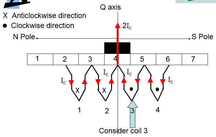
Let us consider a few commutation segments and see process of reversal of current in the coil step by step. Suppose the dc motor to rotating in anticlockwise direction. Observe the direction of current through the coil 3 during the process of commutation. Initially when the coil 3 (commutator segment 4) is under the S pole the current Ic through it is in clockwise direction and through the brush is 2Ic as can be easily deduced from the figure. The brush is in contact with commutator segment 4 completely.
As the motor rotates, brush comes in contact with the CS-5. Total current through the brush remains same but the contribution of C-3 changes to I5 from Ic . Rest of the current goes through the coil.

On further rotation half of the CS-5 comes in contact with the brush , thus there is equal contribution from CS-4 and CS-5 to the brush. Notice the current through the coil 3 will become 0. This is a short circuit condition. If there is even a small amount of induced voltage, it would result in large current through the coil thus damaging the winding.

Further rotation brings majority of the current to brush through CS-5. And the direction of the current in the coil 3 has reversed.

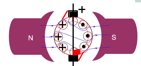
One of the most interesting phenomena that occurs in a DC Motor is armature reaction. Current flowing through the armature creates its own magnetic flux called the armature flux. The action of this armature flux on the main flux set up by the field is known as armature reaction. Let us explain this through a series of diagrams. The excitation of field winding sets up magnetic flux from North Pole to South Pole. When the current flows through the armature winding, the direction of current under one pole face is same and opposite to that of other. It can be clearly seen that the resultant armature flux strengthens the main flux on the top left and bottom right side and weakens it on the other. The resultant flux in the armature region is as shown.


