

NTPC Introduction
National Thermal Power Corporation is one of Navratna of India. It is a coal based power plant. NTPC lights 1 out of every 3 bulbs in India. NTPC Mouda was setup in year 2009. Its 1st stage comprising of 2 units of 500MW was commissioned on March 2013. The 2nd stage comprising of 2 units of 660MW is under erection (scheduled to be commissioned in 2016). This 2320MW Power Plant has the parts and models provided by BHEL (Bharat Heavy Electronics Limited). Two necessary raw materials that a power plant needs for its operation are coal and water. The coal is grabbed from Mahanadi Coal Field or sometimes from the coal belt region comprising of Jharkhand, Chhattisgarh, and Orissa etc. while Goshikhurd Dam (Bhandara District) serves as the source of water.
Outline of a Power Plant
The basic principle behind any thermal power plant is the generation of steam from water to rotate the turbine. The energy required to convert water to steam comes from heating of coal. To be a bit more precise any thermal power plant can be described through four flow paths. These are:
- • Steam
- • Condenser
- • Flue gas
- • Ash
Diagram:

The coal reaching the plant is converted to pulverised coal in CHP. The water from the reservoir is converted to DM form in DM Water Treatment Plant. The coal and water is fed to boiler. Steam is produced due to heating of water. In addition flue gases and ash is produced as a result of burning of coal. The steam goes from boiler to turbine through super heater. The turbine is coupled with a generator which generates voltage. From the generator it goes to switch yard where the voltage is stepped up to desired level and feed to the transmission line.
The steam then needs to be cooled down to be used again. So the steam is passed on to the condenser. For Cooling of steam in Condenser, Cooling water is used, From there Cooling water (CW water) goes to the cooling tower where the temperature falls and water is circulated back in close cycle to the Condenser whereas steam condensed into water is stored in Hotwell again to be used as feed water in boiler. Before reaching the boiler it passes through de-aerator and Heaters and then pumped to the boiler by circular feed water pump.
The flue gas that is produced in the boiler goes through the economiser. Heat in flue gas is used to heat the water. Thus temperature falls. Next stage is an air preheater stage where temperature still falls. The energy is used to heat the air which is required for combustion. Next the cooled flue gas goes to Electrostatic precipitator (ESP) and then the gas escapes from the Chimney.
The ash produced from the burning of coal which settles down are carried to the ash handling plant and removed in the form of slurry.
DETAILED DISCUSSION OF DIFFERENT PARTS OF POWER PLANT
Water Treatment Plant

Power plants need enormous amount of water on hourly basis for normal functioning of plant. They can’t afford to waste water. Also there are restriction imposed by the government on the amount of water these power plant draw form natural source and the waste water the discharge. So every power plant needs to have an efficient water treatment section which would enable them to utilise the waste water most judiciously.
Flow Diagram of WTP

The water from the reservoir is sucked into 3 raw water handling plant and 2 Ash water handling plant. The water is sent to the aerator. The aerator function is to remove the foul odour from the raw water by increasing the surface area. There are 3 clarifier to which the water is moved henceforth. In clarifier alum and lime are added to the water. Alum helps to settle down the solid particles and lime helps to maintain the pH of the water. Clarifier is actually a big tank in which the incoming water is mixed with alum and lime and agitated with the help of shaft with long blade connected to 3 phase induction motor. The solid particles get attracted towards the centre and get collected in concentric cylindrical structure from where it is moved out through duct in the form of slurry. The clear surface water moved down to a water pool. A part of water from the pool is collected and used for Air conditioning (HVAC) and for makeup water for circulating water (CW). The rest is divided into two parts. One is exposed to gravity sand filtering and is collected in sump and after further processing is used as portable water. The other part goes through gravity sand filter and carbon filter. DM water is obtained from it after ion exchange process.
SPECIFICATION
RAW WATER PUMPS

CASCADE AERATOR

CLARIFIERS

DM Plant

After gravity sand filtering the water is passed through activated coal filter. Then we have strong acid cation and weak acid cation tanks where HCl dosing is done to remove cation. Then water goes to digresser where CO2 removal takes place. Then we have strong base anion and weak base anion tank where NaOH dosing is done to remove anion. Then mixed acid base dosing is done to if any alkalinity or acidity is still left. Then the water is collected in DM water tank.

. There are 2 functional streams for portable water and 3 for DM water. A channel from the raw water treatment plant goes to DM aerator. From there it directly goes to the GSF filter and follows the same route as the last process.
The waste water coming from various section of the plant which can’t be further used are treated in lamina separation where the water is slowly stirred with the help blades mounted on shaft of induction motor. A part of the treated water is used for cooling coal and the other is used for cleaning aerator.
Chlorination and sulphonation in done on main stream water going to the condenser. Process is given in chart.

SPECIFICATION
DM WATER TANK

Coal Handling Plant

Coal handling Plant, as the name suggest is responsible for whatever happens to the coal from the point the wagon filled with coal comes to the plant and until the time it reaches the boiler.
The coal which comes to the plant are in the form of large lumps. Coal needs to be converted to fine powdered form to be used in boiler for burning. Powdered form increases the surface area of coal which helps in burning it mostly efficiently. In between the coal needs to be stocked, tested for the calorific value and then sent in a controlled right amount to the boiler. All these steps are managed by coal handling plant.


MAIN PLANT
Details of flow path in main plant

The pulverized coal from the CHP is lifted to the boiler by PA Fan. The coal stays in the furnace for less than 2 seconds. The energy from the burning coal heats up the water running in the tubes lined on the furnace walls. Coexisting heated water and steam moves up to the boiler drum. Here the water separates from the steam. Steam further moves up to the super-heater where it is heated to 540c at which only steam exist. This steam goes to the High Pressure Turbine. The temperature of the steam falls. So it is again heated in re-heater to 340c and moved forward to the IPT and finally to the low pressure turbine. All these turbines are mounted on a common shaft coupled to generator. Now the steam is extracted from LP heaters to the condenser and allowed to cool to 45c. Condensate extraction pump transfers the condensate to the DE aerator through LP heater where dissolved gases like co2 and o2 are removed. LP dosing is done to savage oxygen. It is transfer to feed storage tank. Finally it goes to the boiler drum after being heated again in HP heater (which has steam bleeding from HP turbine) and the economizer.
Boiler

The figure given above is of a boiler. Considering 100% heat generation in the boiler, 12% of it is lost as flame loss. 2% loss occurs at the turbine as mechanical loss and 45% loss occurs at the condenser. 4% additional loss occurs in the generator. So only 39% of the heat generated is utilized for electricity generation. The numerical values given are for production of 1kW in a 500MW plant. Considering this fact, a 500MW plant requires 310Tonnes/hr of coal.

There are 2 types of boiler:
• Fire Tube Boiler
• Water Tube Boiler
Fire tube boiler where used in old steam run trains in which the fire ran through the tube and heated the water outside it. Water tube boiler have water running in the tube. The heat due to fire outside causes them to get converted to steam. This type of boilers are used in power plants.
BOILER GENERAL SPECIFICATION

Components of boiler:
• Furnace
• Boiler Drum
• Super Heater
• Re Heater
• Economizer
Auxiliaries of Boiler:
• PA Fan
• ID Fan
• FD Fan
• Air Heater
Furnace:
Furnace is a place where the pulverised coal burns in sufficient amount of air. The heat generated converts the water in the tubes lined on the wall of the furnace to steam.Specification:
FURNACE SPECIFICATION

Boiler Drum:
Water and steam both co-exist after being heated. In the boiler drum water and steam seperates out. Water flows back through another path while steam moves to the super heater.Specification:
DRUM

Super Heater:
Super Heater has the task of heating the steam to 540 C at which no trace of water is left. This ensures that the blades of turbine are not corroded by water in long run.Specification:
SUPERHEATERS

Reheater:
After the steam is used up in HPT, it loses its energy and begin to condense. Reheater does the task of heating it again but upto 340 C to be used in IPT.Specification:
REHEATERS:

Economiser:
Economiser does the job of utilizing the energy of the flue gases to heat up the water which is used in boiler.Specification:
ECONOMIZER

ID Fan:
ID Fan is used after the ESP to move the flue gas out through the chimney by creating an induced draft. Also they are used in cooling tower for cooling the water.Specification:
ID Fan

FD Fan:
Furnace requires a large quantity of air for efficient burning of the fuel (coal or oil). Forced Draft Fan are used to suck in the air required for efficient burning of fuel in furnace.Specification:
FD FAN MOTOR

FAN DATA

PA Fan:
Primary Air Fan are used to lift the pulverised coal to the boiler for burning.Specification:
FAN

MOTOR

Air Heater:
Fuel (coal) burns more efficiently if the temperature of air is high. For this purpose air is heated before it is used in boiler. Air Preheater does this task. They are divided into two stages:• Primary Air preheater
• Secondary Air preheater
Specification:
PRIMARY AIR PREHEATER (PAPH)
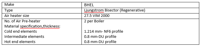
SECONDARY AIR PRE-HEATER (SAPH)

Turbine

Function of the turbine is to convert the heat energy of the steam to rotational energy of the turbine. High pressure steam is allowed to enter the turbine through small orifice. The turbine has 3 set of blades:
• Impulse blade
• Guide blade
• Reaction blade
There are 2 set of impulse blade where the steam first impacts. The structure of the blades are such that steam keeps on oscillating between the fixed guide blades and the movable reaction blades until is it finally moved out of the turbine. This change in momentum produces torque on the rotor blades and the rotor rotates. By the time the steam reaches the last stage in the turbine its pressure and temperature drops to greater extent and it is extracted by the condensate extraction pump.
In a 500MW plant 3 cylinder reheat condensing turbine is used.
HPT:
It has barrel type construction of outer casing. Inner casing has guide valves in it. The inner casing is fixed in both the planes to the outer casing which makes it free to expand radially from the shaft. Barrel construction makes it easier for maintenance. It has 17 reaction stages. It is smallest in size. Turning gears are mounted in front of HPT to rotate the turbine at low speed to have uniform heating or cooling to protect the rotor from distortion or hogging. This turning gear is rotated by the pressure of oil.IPT:
It has double flow construction. The steam from reheater enters the IPT from top and bottom. Upper part and the lower part of the casing are separable. They are joined together by nut bolts. It has 12 reaction stages per flow. The high temperature and pressure remain confined in the inner casing. Outer casing experiences lower temperature and pressure.LPT:
It is also a double flow turbine but with 6 reaction stages per flow. The inner casing is supported on the outer casing in front and rear end. All the three turbines are mounted on a common axis. It is largest in size.Specification:

LOAD

SPEED

Generator

A generator converts the rotational energy to electrical energy. This conversion is based upon the Faraday's Law which states that relative motion between conductor and magnetic flux induces emf in the conductor.
Generator or alternator consist of stator and rotor. But unlike DC machines the AC generator/ alternator have poles which rotate while the armature remain fixed to the stator. Depending upon the construction there are 2 types of rotor:
• Salient Poles
• Cylindrical Poles
Salient Pole rotor have number of projected pairs of laminated poles bolted on the magnetic wheel while the Cylindrical Poles have numerous cylindrical slots in which field winding are wound. The excitation current to the field winding or the magnetic poles is given by exciter.
The alternator used in NTPC plant is a cylindrical types which rated speed of 3000rpm. Stator winding is star connected. It produces active power of 500MW at .85 lag at rated rpm. The stator winding are water cooled while the core and the rotor are hydrogen cooled. The output voltage produced is 21KV.
Specification:
GENERAL

RATED DATA

Exciter:
Excitation current is required to set up the working magnetic flux in the alternator. This necessary excitation current is provided by the exciter. It is transferred to the magnetic poles or field winding through slip ring. The output of the ac exciter is given to rectifier wheel. It rectifies the current and feeds it to the field winding through the slip ring.There are 3 types of exciter:
• Static exciter
• Brushless exciter
• Pilot exciter
Specification:
EXITATION SYSTEM
A)Main Exciter

B)Rectifier Wheel

C) Pilot Exciter

Oil Handling Plant

For balance of plant an oil handling plant is very essential. Oil is required as lubricant. Also for starting the combustion after a shutdown, oil is required as fuel.
Components of OHP
AOP (Auxiliary oil pump): There are 2 AOPs. They are required for lubrication of bearing or turning gears and motor gears.
MOP (Main oil pump): It is single in number. AC motor pump and mechanical pump mounted on the turbine shaft in front of the HP turbine constitute MOP. It comes in service when the turbine achieve its full speed. AOP is closed when MOP starts.
DC oil Pump: It is an emergency oil pump. It supplies oil when AOP and MOP are not in service.
Jacking Oil Pump: They are two in number. They are used to jack or lift the rotor in initial condition when the rotor is required to be rotated.
Ash handling Plant

Burning of coal produces ash. The ash on getting collected on the walls would reduce the efficiency of the power plant. So they need to be removed.
Bottom Ash Removal
For the removal of the bottom ash that get collected in the furnace, the boiler has a many funnel shaped structure called Hoppers. The settled ash at the bottom keep on getting drifted to the due to funnel shape and get collected. The collected ash is mixed with water to form slurry and is moved out of the plant.Fly ash removal system
For the removal of ash content from flue gas we have Electrostatic Precipitator. It has two large parallel plates to which high DC voltage is applied. The ash particles in flue gases when pass between them get polarised and get attracted to the plates. The stuck particles on the plates is removed by rapping mechanism. It is mechanical process of hitting the plates with hammer. Also there are hoppers at the lower end of APH, ESP etc. for collection of ash content that may get collected there. The ash is collected and made into slurry and moved out of the plant.
Switch Yard

The voltage obtained from the generator as such fed to the grid. They need to be stepped up. To fulfil this need Switch Yard is required.
NTPC has 2 switch yard of 400kV and 132kV. These two switch yards are interlinked together through two auto transformers. There are three generating transformer for each phase (RYB). The MVa rating of these transformers depend upon the rating of the generator. The generator installed in ntpc is 588MVa. So all the three phase transformer are 200MVa each.
They step up 21kV at the generated end to 400kV to be transferred to the transmission lines. Step down transformer of 400:132 is used to send electricity to the township. Also there are separate transformers for khaparkheda, wardha etc.
Details of auxiliaries at Switch Yard
1. Transformer
2. Bus bars
3. Circuit Breakers
4. Current Transformers(for auxiliary)
5. Potential Transformers(for auxiliary)
6. Isolators
7. Lightening Arresters
8. Insulators
9. Control Room Containing various auxiliaries
10. DC Battery
Transformer:

Transformers are required to step up or step down the voltage level depending upon the requirement. They are constant flux device. A basic transformer has two sets of winding namely primary and secondary winding. Ratio of number of turns in both winding determine whether it is step up or step down transformer.
Working Principle:
At the most ground level transformer is just an application of Faraday's Law which states that emf is induced in a coil if the magnetic flux linked to it changes.Alternating current given to primary winding of transformer produces alternating flux. This alternating flux is linked to the secondary through a common core. The alternating flux through the turns of the secondary winding induces emf in the winding. If the number of turns are greater then the voltage is stepped up, else it is stepped down.
Cooling:
Heat loss through the transformer occur in the form of hysteresis loss, eddy current loss, copper losses etc. This heat loss tend to increase the temperature of transformer which could be fatal after certain limits. So cooling mechanism is required.
Small transformers generally have natural air cooling, while transformer with high power rating have air forced and oil natural cooling in addition. Still larger transformer have oil forced cooling as well.
Different rating of transformer are required at various parts of power plant. They are:
• Generator Transformer
• Station Transformer
• Unit Transformer
• Offsite Transformer
Important Accessories of transformers:
1. Buchholz relay
2. Conservator
3. Silica jell breather
Conservator
Now it happens that the oil which is circulated through the transformer for cooling may expand or contract depending upon the varying temperature and pressure condition to which it is exposed. In summer there is an expansion of the oil. If suitable arrangement is not made for the storage of excess oil, then the oil tube may bust. On the other hand, in winter season, due to contraction, the availability of oil necessary for cooling the transformer will be less leading to shortening of the life of transformer. Here comes the action of conservator. The conservator stores the oil in case of expansion and provides the deficit amount in winter.Action of Buchholz Relay:
Buchholz relay is a mechanical actuator, which trips the transformer in case of internal faults like insulation breakdown, short circuit of winding etc. Due to these faults the temperature rises and there is decomposition of insulating oil and gases are produced which get accumulated in the upper part of the Buchholz relay. This leads to tilting of the mercury switch. Based upon the level, the alarm is produced and relay comes in action.The operator in control room receives an alarm, the transformer is turned off. The mouth of the gas valve on Buchholz relay is opened and a match is lighted. If the gas escaping the transformer catches fire, then this is an indication that the winding have burned and it requires immediate maintenance. On the other hand if it does not catch fire, then it is an indication that air was collected. The air is allowed to escape and the normal function of the transformer is resumed.
Silica jell breather
One of the biggest enemy of transformer is the moisture. To deal with these, the transformer are provided with silica jell box. It is blue in colour. As it absorbs moisture it becomes pinkish. Then it is required to be replaced. They can be reused after placing them in light for some time. They lose their moisture content and become blue again and ready to be reused.Details of various transformer are as under:
GENERATOR TRANSFORMER
STATION TRANSFORMER
UNIT TRANSFORMER
Bus Bars:
The bus bars are aluminium or copper conductors which carry electric current in open air to which various connection (feeders, equipment) can be made. There arrangements are such that work on any equipment can be done without causing any trouble to incoming and outgoing feeders.Specification:
BUS BAR

Circuit Breakers:
Circuit Breakers used for making and breaking of electrical contacts. This task can’t be done in open air as this high voltage will ionize the air and produce spark. Circuit breaker contains inert medium like vacuum or SF6 in which the making and breaking of contact is done. Their outer cover is made of porcelain. Also they ensure that the operation is done very fast so that arc is quenched faster. Before the circuit breaker is operated, it is necessary to ensure that correct pressure is maintained in the circuit breaker and the gas cylinder.Specification:
400 KV CIRCUIT BREAKERS

11KV CIRCUIT BREAKERS (VACUUM TYPE)

3.3KV CIRCUIT BREAKERS (VACUUM TYPE)

Isolators:
Isolators are disconnection switch. They can be controlled from switch yard or from the control room. These isolators are in open air, so they are used only in no load condition ie. they are operated only after the circuit breaker is brought to action. By looking at the position of the isolators we can tell whether it is connected or disconnected. For repairing purpose circuit breaker is tripped first and then the isolators contact are removed which isolates the equipment for repair purpose.Specification:
400 KV ISOLATORS

Current Transformer and Potential Transformer:
For the safety of the instruments and economic reasons, we need to keep a record of the current and voltage at various points in the circuit. Such high voltage and current is highly unsafe to directly give to the measuring equipment. Their values have to be lowered down. For this we require CT and PT. These can be seen at various points in the switch yard. These are step down transformers.400 KV CAPACITIVE VOLTAGE TRANSFORMER (PTs)

400 KV CURRENT TRANSFORMER (CTs)

Insulators:
The heavy current carrying conductors if directly mounted on the poles or support will directly ground them to earth. So we requires some insulator through which we can hang them on poles and propagate them. The insulators should have high resistivity to prevent the leakage of current to earth. Along with this it should be able to withstand the weight of the conductor (wire). Depending upon the rated kV the line is carrying the size of conductor changes so does the insulator required to support them. For 33kV and below we use pin type insulator and for higher rating we use suspension type insulators. These insulators have porcelain covering. These have discs whose number depend upon the kV rating of the line. Eg. If the discs are of 11kV rating, then we would require 20 of them to hang the conductor through the support.Lightening Arrester:
Lightening arresters protect from surge due to switching the machines on and off and due to lightening. They have nonlinear resistance whose conductivity increases with increase in voltage above the safe value. A 400kV transformer can sustain voltage up to 500kV. Above this limit the resistance path of arrester become conductive and conduct the surge current to the ground without harming any equipment.Specification:

Control room:
It has arrangement for the remote monitoring of each of the auxiliaries, feeders etc. and controlling them. The office has single line diagram of the switch yard. Also the power being sent to various parts and the generated power, power factor etc. displayed on the screen.DC Battery:
For the proper functioning of the relay and other protective gears we requires uninterrupted dc supply. They are crucial even when the whole grid terminates. We have 2 banks of 169 cells each of 1.4V summing up to 220V battery in NTPC. Along with this we have 48v battery for PLCC with 2 banks with 38 cells each.Specification:
220 V BATTERY

220 V BATTERY CHARGER

BATTERY FOR PLCC

COOLING TOWER

In the processes of condensing the steam, the circulating water in the condenser gets heated. This heated water needs to be cooled down in order to be used again in the condenser. Here comes the role of cooling tower. The cooling tower takes the circulating water from the condenser cools it and returns it through the main stream.
There are two types of cooling tower:
• Natural Cooling tower
• Induced draft cooling tower
Natural Cooling tower required comparatively large tower height for cooling by the same temperature. Also they are bit risky and unsafe compared to Induced draft cooling towers.
The cooling towers used in NTPC are Induced draft type. These towers are of 100 - 110 m height. There are 9 individual tower in each set. A 30kW 3phase induction motor drives the ID fan through a long shaft coupled to a set of gears with gear ratio 12:1. Below the 4 blade ID fan, there are elevator and networks of small pipes through with the incoming hot water flows. These pipes have nozzles below them and layers of pvc v bar arranged in slant fashion. For collecting cool water the base is made 3m deep. It has an outlet connecting it to the open main channel.
Functioning:

The circulating water from the condenser comes from the through large tubes under pressure enough to give them a head of 90m. Water from here get distributed among a number of small pipes network just below the Induced Draft fan. The nozzles at the bottom end of the pipes breaks the water and sprinkles them on the pvc v bar layer. This water falls on the bed in the form of splendid shower in 
There are two temperature sensors available in cooling tower system. One for the inlet water (hot) and other for the outlet water (cool). The temperature noted at that instance was 39c for inlet and 29 c of the outlet.
The rubber system is used for coupling the shaft and motor. Proper alignment is essential. As the length of shaft increases, the accuracy required also get increased. The accuracy in this case was .001m in up, down, left, right direction.
The opening and closing of the valve for water, and supply to motor are remotely controlled from DCS. Also they are controls available on site but rarely used. Protection against vibration, over speed, overcurrent etc. are provided.


The training course just completed on 21 st December 2013. Snap shots of the program are here. cpcs-training-courses.co.uk
ReplyDelete